Oscilloscope For Arduino Uk
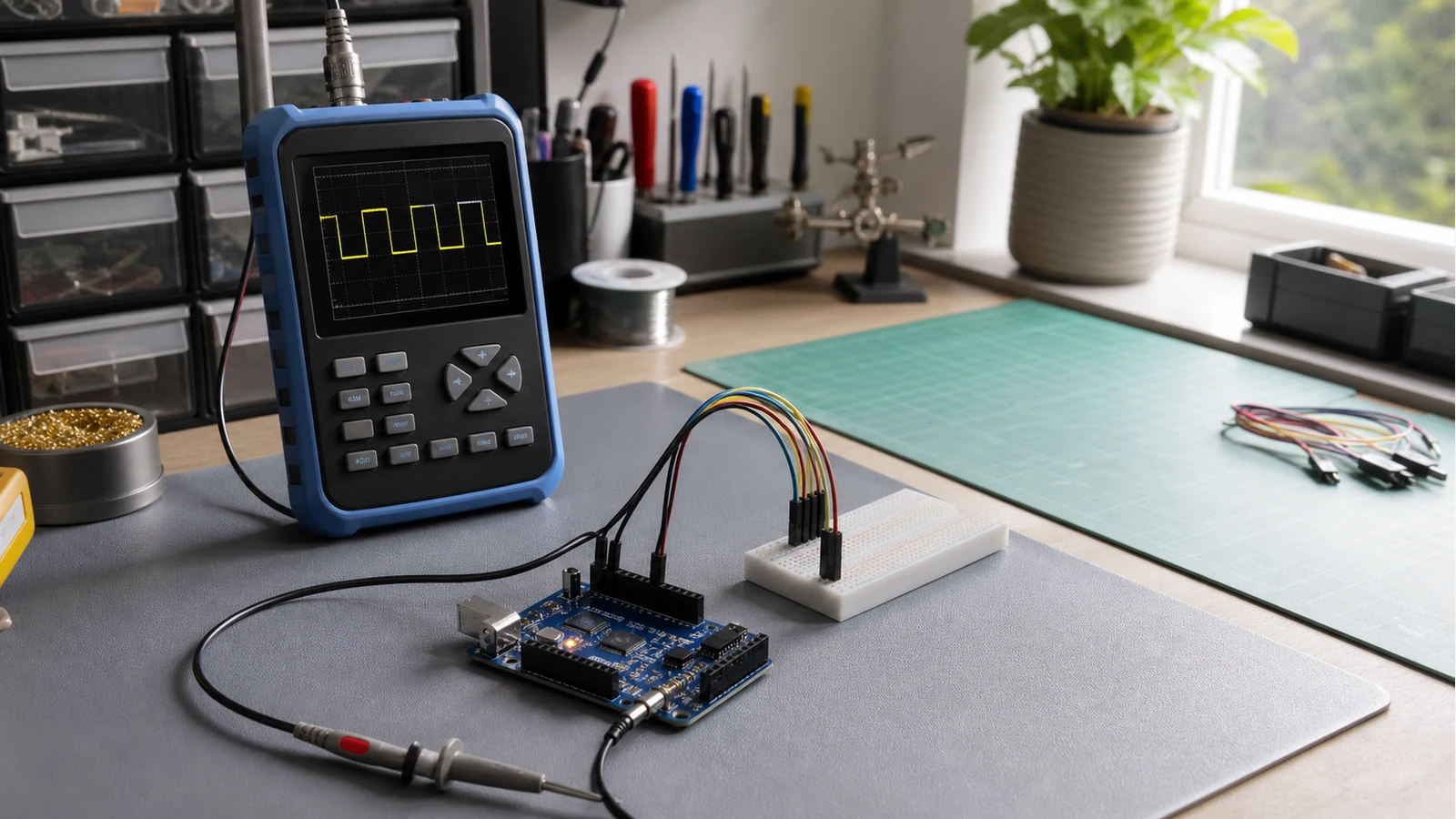
Direct answer: a portable oscilloscope is useful for Arduino work when you want to see GPIO switching, PWM duty cycle, slow analogue sensor behaviour and basic serial activity. It is not a replacement for a logic analyser or a high-bandwidth bench scope when the job is deep protocol decode, very fast SPI edges or multi-channel timing.
What an Arduino scope needs to show
For most UK maker benches, the first question is not brand prestige. It is whether the instrument lets you see the signal clearly enough to make the next decision. A useful Arduino scope should let you set a stable trigger, adjust volts per division, adjust time per division and freeze the waveform without forcing you to clear space for a full bench lab.
PWM is the easiest win. The scope shows the high time, low time and period, so you can see whether a dim LED, motor driver input or servo-style control signal is doing what the sketch says. If PWM is your main task, read the separate PWM measurement guide before buying anything.
Signals a portable scope can usually help with
- GPIO toggles: confirm that a pin is actually switching and that the level is plausible for the circuit.
- PWM outputs: inspect duty cycle, frequency and whether the waveform is stable.
- Analogue sensors: see slow ramps, noise, dropouts and supply-rail movement.
- UART and I2C presence checks: confirm activity and rough shape, while remembering that decoding bytes is a different job.
UK hobby retailers commonly position pocket scopes around Arduino, ESP32 and similar bench debugging, but that should be read as a use-case fit, not proof that every model can decode every bus. Treat the scope as a visual signal tool first.
Where a handheld starts to run out
A 10MHz-class handheld can be enough for slow microcontroller education and quick maker checks, but it should not be oversold. Fast SPI, sharp edges, radio work and mixed-signal timing across several channels can demand more bandwidth, deeper memory or a dedicated logic analyser. If your fault is “what exact byte crossed the bus?”, a scope trace may only tell you that traffic exists.
Probe choice matters too. A poor X1/X10 setting can make a good circuit look wrong. Before trusting any Arduino waveform, run through the X1 vs X10 probe checklist.
First captures to try
- Connect ground to the circuit ground before touching the probe tip to the signal.
- Start with a simple GPIO blink sketch and trigger on a rising edge.
- Move to PWM and adjust the timebase until one to three cycles fill the screen.
- Check a sensor output while moving the sensor slowly, looking for dropouts rather than perfect textbook curves.
- Only then try bus lines, treating the trace as a physical-layer check rather than full protocol analysis.
Should you buy a handheld for Arduino?
Proceed if your main pain is seeing real waveforms on a small desk, garage bench or shared college table. Pause if your projects already depend on high-speed digital buses, multiple simultaneous channels or software decoding. For a laptop-centred workflow, compare the trade-offs in the USB oscilloscope vs handheld guide.
If your conditions are simple bench debugging, PWM checks and portable learning, a standalone handheld scope can be a sensible next step. Probeo's verified same-site product route is available for readers who specifically want a portable screen-in-hand option: view the handheld oscilloscope detail page.
Sources
- Kunkune UK: UK retailer positions pocket scopes for Arduino/ESP32 PWM, UART and I2C debugging on hobby benches.
- Electronics Stack Exchange: Practical PWM capture guidance emphasises shared ground, DC coupling and edge trigger setup.
- Hanmatek guide: Beginner PWM measurement flow: probe ground, AUTO/timebase, then frequency and duty cycle reads.