How To Measure Pwm With Oscilloscope Uk
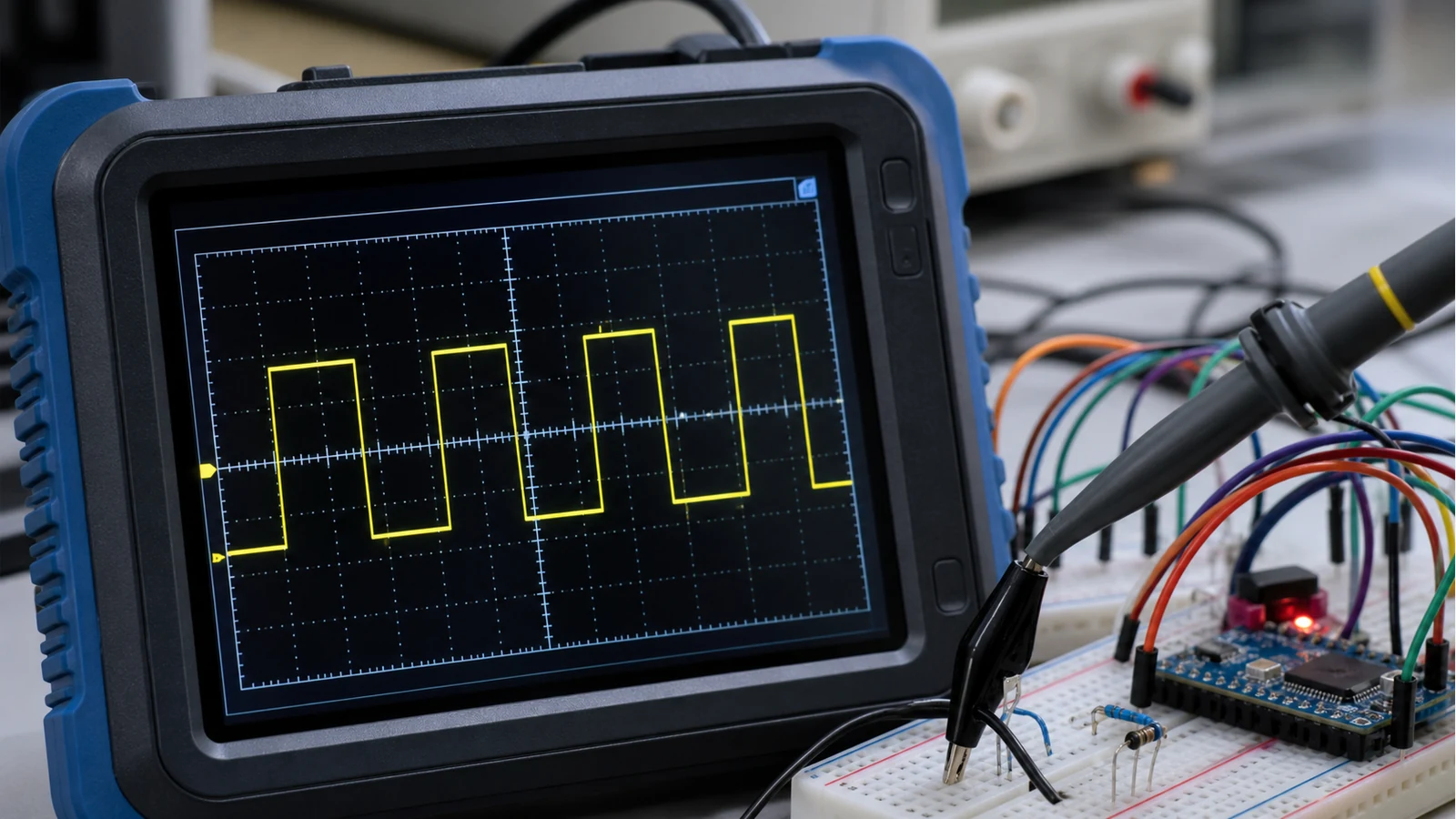
Direct answer: to measure PWM with an oscilloscope, connect the scope ground to the circuit ground first, use DC coupling, trigger on a rising or falling edge near the middle of the waveform, then read the period, frequency and duty cycle from the stable trace. Stop if you are unsure about grounding, mains reference or high-energy automotive circuits.
Why a multimeter can mislead
A multimeter often reports an average or processed value, which can hide the real shape of a PWM signal. A scope shows whether the signal is clean, noisy, intermittent, inverted or clipped. That matters in Arduino projects, motor controls, lighting circuits and vehicle actuator diagnostics.
PWM capture checklist
- Identify ground. Do not guess. On a breadboard, use the circuit ground rail. On vehicles, follow service information and avoid high-energy circuits.
- Use DC coupling. PWM level and duty both matter, so you usually want to see the real high and low voltage levels.
- Set volts/div. Start wide enough to keep the full waveform on screen, then zoom in.
- Set time/div. Aim to show one to several complete cycles, not a compressed block of activity.
- Trigger on an edge. Place the trigger level between the low and high states so the trace stops sliding.
- Read period and duty. Frequency is the inverse of period; duty cycle is high time divided by total period.
Arduino versus automotive PWM
On Arduino and breadboard circuits, the main risks are usually wrong ground, wrong probe setting and timebase confusion. Automotive PWM adds electrical noise, moving harnesses, manufacturer-specific wiring and safety constraints. UK workshop guidance on voltage, timebase and trigger setup is useful, but pass/fail values still come from the vehicle maker, not a generic blog article.
Common mistakes
- Using AC coupling and then wondering why the level looks wrong.
- Clipping the ground lead far from the signal return and adding noise.
- Expecting a multimeter duty-cycle mode to show intermittent dropouts.
- Assuming every PWM signal has the same voltage, frequency or duty range.
- Measuring a circuit before checking probe attenuation; use the X1/X10 probe guide if in doubt.
When a handheld is enough
A handheld scope is enough when you need to confirm basic PWM shape, frequency, duty and intermittent behaviour at modest speeds. It is not enough when you need deep memory, automated protocol analysis, several synchronised channels or formal diagnostic reporting. For microcontroller work, the Arduino scope guide explains the practical boundary.
Stop conditions
Stop and get qualified help if the circuit may be mains-referenced, if the vehicle circuit involves ignition, high-voltage hybrid systems, piezo injectors or other high-energy sections, or if you cannot identify a safe ground. A stable trace is not worth a damaged tool, vehicle module or injury.
Sources
- autotechnician: UK trade article explains voltage, timebase and trigger setup for stable automotive waveforms.
- Pico Automotive Library: Documents PWM analysis techniques for automotive diagnostics beyond simple multimeter averages.
- Electronics Stack Exchange: Community how-to covering ground connection, DC coupling and edge trigger for stable PWM captures.
- Rohde & Schwarz: Application note on analysing PWM parameters and modulation behaviour on oscilloscopes.