Crank and Cam Sensor Waveform Test Workflow
Plan a documented comparison to trusted service information without inventing a universal good waveform.
Short answer: A useful crank/cam test records vehicle identity, fault conditions, wiring information, supply/reference checks, probe points, channel scales and engine state. Compare with trusted service information for the exact engine. There is no universal “good waveform” that proves every crank or cam system healthy.
This is a working guide for workflow, not a rewritten product card. Begin with the current Probeo BSIDE 10 MHz handheld oscilloscope product page, then keep the exact manual, label or service information beside the task so a live specification is never mistaken for proof of the final result.
The decision this page helps you make
Plan a documented comparison to trusted service information without inventing a universal good waveform. That means defining a pass condition before buying, fitting or using anything. If the necessary identity, safety limit or acceptance evidence is missing, the honest outcome is to pause rather than turn uncertainty into a confident claim.
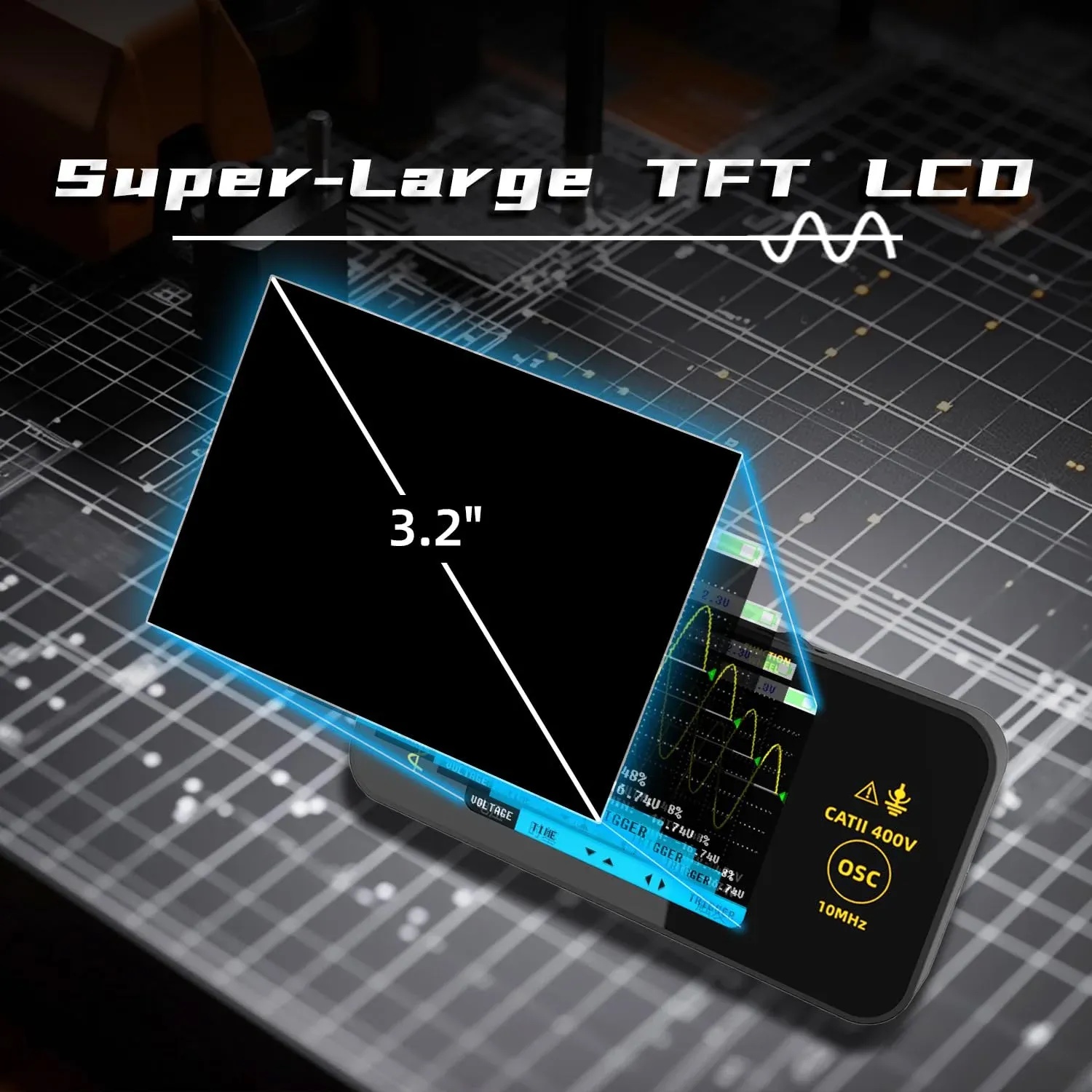
The product page currently says: The seller lists 10 MHz bandwidth, 48 MSa/s sampling, 1 Mohm input, a 3.2-inch 320x240 display and 1,500 mAh USB-C battery. The product is a BSIDE handheld described as an alternative to Hantek; that wording is not a claim of Hantek manufacture or equivalence. These are useful purchasing inputs, but they remain seller-provided specifications until the exact delivered item and current documentation agree.
The non-negotiable boundary is equally important: Oscilloscope inputs and grounds can create dangerous shorts or exceed the instrument rating. Verify the exact manual, probe attenuation, maximum input, reference-ground arrangement and circuit category before connection. Automotive suitability is application-specific, not proven by a broad product label.
A practical step-by-step workflow
- Step 1: Record vehicle, engine, fault codes and symptom conditions.
- Step 2: Obtain the exact circuit diagram and expected sensor type.
- Step 3: Check power, ground and reference with the appropriate tool.
- Step 4: Choose safe back-probe points and channel references.
- Step 5: Set scales from expected signal, then crank or run only as planned.
- Step 6: Save the full capture with timebase and trigger settings.
- Step 7: Compare sync, amplitude and dropout evidence to exact service information.
Carry out the checks in order. For this specific decision, record the exact identity, the starting condition, the setting or method used and why the outcome was accepted or rejected. That turns a later change into something that can be diagnosed instead of an anecdote.
Evidence table
| Evidence layer | Question | Avoid |
|---|---|---|
| Circuit basics | Are supply, ground and reference present? | Skipping directly to waveform shape |
| Crank signal | Are pulses present and stable under symptom conditions? | Inventing a universal amplitude |
| Cam relationship | Does timing agree with exact engine reference? | Comparing unrelated engine screenshots |
| Repeatability | Does the fault recur with the same setup? | Changing settings and calling captures comparable |
Use the table as a stop/go record. When the current manual or service information gives a specific limit, that exact source takes priority over this general guide.
What the listing can and cannot prove
For Probeo BSIDE 10 MHz handheld oscilloscope, the listing can establish the current offer and the seller’s stated specification. It cannot independently establish the result described in this article. Ratings, discount badges and scarcity messages are not technical evidence. Where two statements conflict, preserve both, ask for written clarification and postpone irreversible work.
Common failure modes
- Diagnosing a sensor before checking wiring and supply.
- Using an image-search waveform as specification.
- Saving only a cropped screenshot.
- Failing to record timebase and volts/div.
- Back-probing in a way that damages seals.
- Calling correlation proof of mechanical timing without the correct reference.
A documented stop decision protects the item and the diagnostic trail. It also makes a supplier question or return easier because the mismatch was recorded before damage or modification.
How this page fits the wider topic cluster
Use the product page for the current offer. Continue to automotive diagnostic oscilloscope uk guide, handheld oscilloscope uk buying guide, oscilloscope bandwidth sample rate automotive, automotive oscilloscope probe safety grounding only when that adjacent question becomes relevant. Together these pages cover buying, setup, evidence, maintenance and safety without repeating one broad buyer’s guide under several titles.
Frequently asked questions
What is the first check for this task?
Record vehicle, engine, fault codes and symptom conditions. This first check matters because the rest of the workflow assumes the correct item, information and starting condition.
What result should be written down?
Record the result of “Compare sync, amplitude and dropout evidence to exact service information.” together with the exact item or batch, relevant settings and any photograph or measurement that another person would need to repeat the decision.
Which product claim still needs verification?
The seller lists 10 MHz bandwidth, 48 MSa/s sampling, 1 Mohm input, a 3.2-inch 320x240 display and 1,500 mAh USB-C battery. The product is a BSIDE handheld described as an alternative to Hantek; that wording is not a claim of Hantek manufacture or equivalence. Treat each figure or compatibility statement as seller-provided until the delivered label and current documentation agree.
What is an immediate stop signal?
Diagnosing a sensor before checking wiring and supply. is one avoidable failure. Also stop whenever oscilloscope inputs and grounds can create dangerous shorts or exceed the instrument rating. Verify the exact manual, probe attenuation, maximum input, reference-ground arrangement and circuit category before connection. Automotive suitability is application-specific, not proven by a broad product label.
Sources and scope
The product specifications in this article are attributed to the live seller page. Decision and safety boundaries were checked against these primary or authoritative sources:
These sources define principles within their stated scope. They do not endorse Probeo BSIDE 10 MHz handheld oscilloscope, and no cited organisation is represented as having tested it.
Bottom line
A useful crank/cam test records vehicle identity, fault conditions, wiring information, supply/reference checks, probe points, channel scales and engine state. Compare with trusted service information for the exact engine. There is no universal “good waveform” that proves every crank or cam system healthy. Read the exact instructions, decide what evidence would count as success, and keep a written stop rule. That is the difference between a useful topic-cluster article and a confident-looking product paraphrase.