Crankshaft Sensor Oscilloscope Test Uk
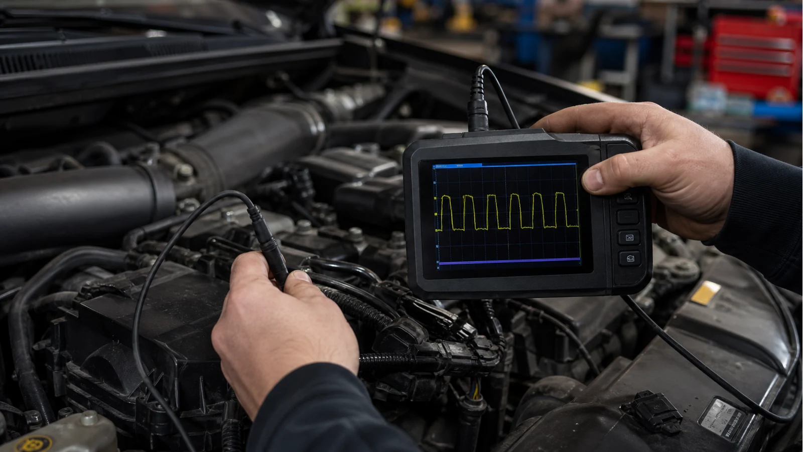
Direct answer: for a crankshaft sensor oscilloscope test, identify whether the CKP sensor is Hall-effect or inductive, connect safely using vehicle service information, capture the signal during cranking or running, then inspect the pattern for consistent edges, amplitude behaviour and missing-tooth reference integrity. Do not use generic voltage thresholds as universal pass/fail rules.
Why fault codes are not enough
A P0335-type code can point you towards the crankshaft position circuit, but it does not prove the sensor alone is faulty. Wiring, connector tension, air gap, trigger wheel condition, power supply and ECU input faults can all affect the result. The oscilloscope helps because it shows the waveform the control unit is trying to interpret.
Diagnostic ladder
- Identify the sensor type. Hall sensors usually produce a square-wave style output; inductive sensors produce an AC waveform whose amplitude changes with speed.
- Check service information. Confirm pinout, supply, ground and expected test method for that vehicle.
- Back-probe safely. Avoid damaging terminals, insulation or control modules.
- Capture while cranking. If the engine does not start, cranking data may still show whether a pattern exists.
- Capture at idle if possible. A running waveform can reveal stability and missing-tooth regularity.
- Compare pattern integrity. Look for dropouts, irregular gaps, collapsed amplitude or distorted edges, then confirm with known-good data when available.
Hall versus inductive patterns
Hall-effect CKP sensors are commonly discussed as square-wave outputs with defined switching behaviour. Inductive crank sensors are commonly shown as sine-like AC waveforms, often with a missing-tooth reference pattern. Public automotive guidance from Pico, TiePie and HELLA is useful for recognising these families, but the correct interpretation still depends on the engine and manufacturer data.
Limits of a simple handheld scope
A simple handheld can be useful for a first look at a crank signal in the bay because it is quick to connect and easy to hold. It is not a full substitute for a multi-channel automotive oscilloscope when you need cam/crank correlation, relative compression, long captures or guided automotive software. If your job is general PWM rather than CKP diagnosis, use the PWM measurement guide instead.
Stop conditions
Stop if you cannot identify the circuit, if the vehicle is hybrid or high-voltage and you are not trained for that system, if the probe setup risks shorting adjacent pins, or if the waveform conflicts with manufacturer information. Also avoid resistance testing Hall sensors unless the service procedure explicitly allows it; the wrong test can mislead or damage electronics.
Sources
- Pico Automotive Guided Tests: Documents Hall-effect CKP running test method, square-wave behaviour and related DTC families.
- TiePie Automotive: Shows inductive crankshaft sensor measurement approach and missing-tooth reference behaviour during cranking/idle.
- HELLA Tech World: Explains inductive vs Hall crankshaft sensor checks and when oscilloscope waveforms are more meaningful than resistance alone.
- autotechnician: UK workshop context for setting voltage/timebase/triggers on automotive sensor captures.